Practical, easy-to-understand welding guidance, real-world examples, and tools to help improve weld quality, productivity, and compliance. For welding professionals including welders, supervisors, inspectors, engineers, and business owners.
4 Common welding discontinuities that pass visual inspection
|
Trouble with text or images? View this article in your web browser Hello Reader One of the most persistent challenges in welding quality is that many serious problems are not obvious at the surface. In the previous articles in this series, we established that welding quality is created through procedures, qualification, and process control—not inspection alone. Visual inspection remains an important quality tool, but it has inherent limitations that are often underestimated. This article is part of the Welding Quality – From Inspection to Control series, which examines how welding quality is managed in real fabrication environments. The series hub provides an overview of how these topics connect and why inspection must be supported by upstream controls. Why Visual Inspection Has LimitsVisual inspection is fast, inexpensive, and widely used. It is effective for identifying surface-breaking discontinuities and obvious workmanship issues. It can be performed not only by inspectors, but by welders, supervisors and other shop personnel. However, visual inspection cannot reliably detect:
This limitation is not a failure of inspectors—it is a limitation of the method itself. When visual inspection is treated as the primary quality gate, defects that affect performance can remain undetected until they cause rework, delays, or failures in service.
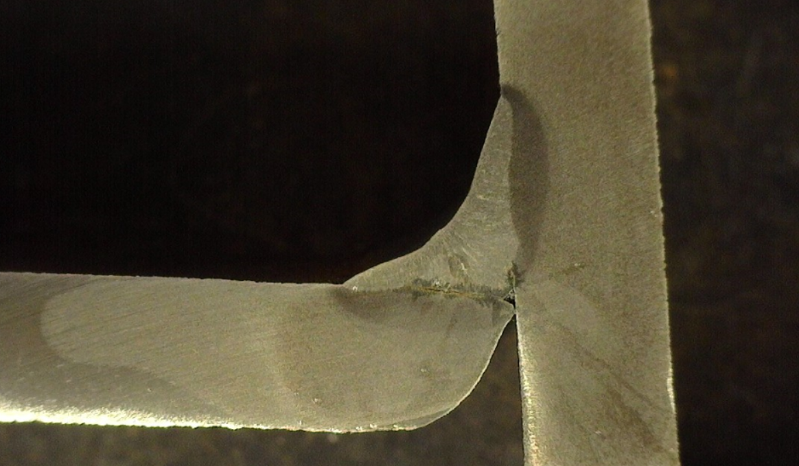
Lack of FusionLack of fusion is one of the most common and most serious welding discontinuities that passes visual inspection. A weld may appear smooth and uniform while failing to properly fuse to the base metal or between weld passes. This is especially common when:
Because the weld surface can look acceptable, lack of fusion is often discovered only through destructive testing, volumetric NDT such as ultrasonic testing (UT) or radiographic testing (RT), or failure in service.
Inadequate PenetrationIn groove welds, especially complete joint penetration (CJP) joints welded from both sides, inadequate penetration can severely reduce load-carrying capacity. Incomplete penetration results in a smaller effective throat. Externally, these welds may appear to meet size and profile requirements. Internally, however, the root may not be fully penetrated due to:
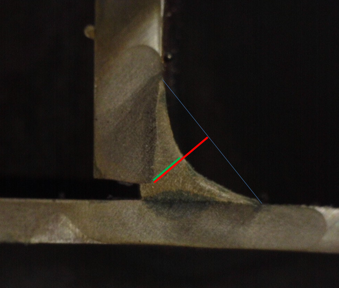
Visual inspection alone cannot confirm penetration depth. Undersized Effective ThroatExcessive weld reinforcement can mask an undersized effective throat, particularly in fillet welds. A large, convex weld may look robust while providing less effective throat than required. This condition often results from:
The weld appears “heavy,” but its load-carrying capacity may be significantly lower than assumed. Many times, fillet welds with excessive reinforcement are cold weld with lack of fusion. A concave weld can sometimes result in an undersized weld throat but many times goes undetected due to incorrect measuring of the weld. Such welds should not use the standard the fillet gauge, but rather use one for concave welds.
Internal Cracking and Metallurgical IssuesCertain cracking mechanisms—such as hydrogen-assisted cracking or solidification cracking—may not be visible at the surface during initial inspection. These issues are influenced by:
Without proper procedure control and awareness of material behavior, these problems can develop even when visual criteria are met. Why These Discontinuities Are So CommonDiscontinuities that pass visual inspection often occur when:
When upstream controls are weak, inspection becomes the last—and least effective—line of defense. The Role of Process Control in Preventing Hidden DefectsPreventing these discontinuities requires control, not just detection. Effective prevention includes:
When these controls are in place, visual inspection becomes confirmation rather than discovery. Practical Tools to Reduce Quality EscapesFree Resource: Welding Quality ChecklistA free Welding Quality Checklist is available to help verify key quality-related items before welding begins, during production, and after completion. The checklist is designed to catch common conditions that lead to lack of fusion, inadequate penetration, and other hidden defects before they become costly problems. Welding Quality Control Standard TemplateFor shops experiencing recurring quality escapes, a checklist alone may not be enough. The Welding Quality Control Standard Template provides a complete, editable framework for defining how welding quality is controlled across procedures, qualification, inspection, and corrective action. This template helps move quality control from informal practices to a documented, repeatable system aligned with AWS codes and industry best practices. |


Welding Answers
Practical, easy-to-understand welding guidance, real-world examples, and tools to help improve weld quality, productivity, and compliance. For welding professionals including welders, supervisors, inspectors, engineers, and business owners.
Trouble seeing text or images? View this article in your web browser Hello Reader, We constantly hear welding experts, welding engineers, CWIs and other industry professionals say that concave fillet welds are bad and should not be allowed. This is a hard stance that may be supported by field failure, but more often than not only by anecdotal evidence. However, it is worth noting that a concave fillet weld is not necessary a problem and sometimes it provides a desirable bead profile. The...
Troulbe with text or images? View this in your web browser Hello Reader Most fabrication shops don’t struggle with welding because they lack capability. They struggle because of the decisions they make every day—especially when those decisions are based on habit rather than engineering and economics. One of the most common examples is electrode selection. Many shops default to using flux-cored wire for everything, assuming it provides the best combination of quality and productivity. Others...
Trouble with text or images? View this article in your web browser Hello Reader If you are a Certified Welding Inspector (CWI), welding engineer, or anyone responsible for interpreting welding codes, you have likely encountered situations where the code language is not completely clear. Many of the questions we receive from readers are related to interpreting welding codes and standards such as AWS D1.1 Structural Welding Code – Steel. In many cases the challenge is not simply understanding...